A few weeks ago, my parents picked up some new shelves they wanted to use for decorations. While helping them set everything up, my father and I quickly realized the shelves would look much nicer with lighting. LED strips immediately came to mind — simple, clean, and easy to control with an ESP8266 running ESPHome.
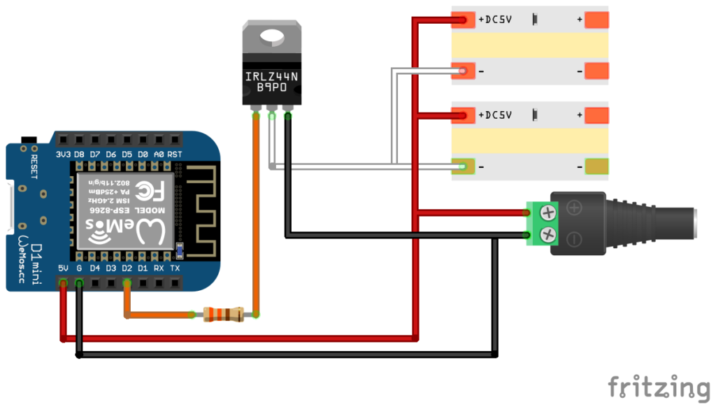
I sketched out a quick design and got to work. The only oddity was that I ended up using an IRLZ44N MOSFET, which is wildly oversized for this project but the best choice I could find for 3.7v logic control. Because of the shelf layout, I also decided to run two LED strips in parallel.
Materials
Most of the parts came from my existing stash, but I did need to buy the LED strip, power supply and transistors.
- ESP8266 (Wemos D1 Mini clone) – pack of 10 from Amazon
- 6.56FT 640LEDs 5V LED Strip – from Amazon
- 5V 3A 15W Power Supply Adapter – from Amazon
- IRLZ44N MOSFET Transistor – pack of 10 from Amazon
- 330 ohm Resistor – pack of 100 from Amazon
- 22 AWG solid core hookup wire – for sensor connections (from Amazon)
- Breadboard & jumper wires – for prototyping
- Soldering iron – to make permanent connections
- 3D printer (Creality CR-6 SE) – for controller and sensor cases
Optional but nice to have:
- Heat shrink tubing – to clean up exposed joints (from Amazon)
- JST connectors & crimping tool – for detachable, neat wiring (from Amazon)
- Proto board – for organizing components and wiring (from Amazon)
- Mount Screw Terminal Block Connector – for cleaner proto board connections (from Amazon)
Flashing the Board
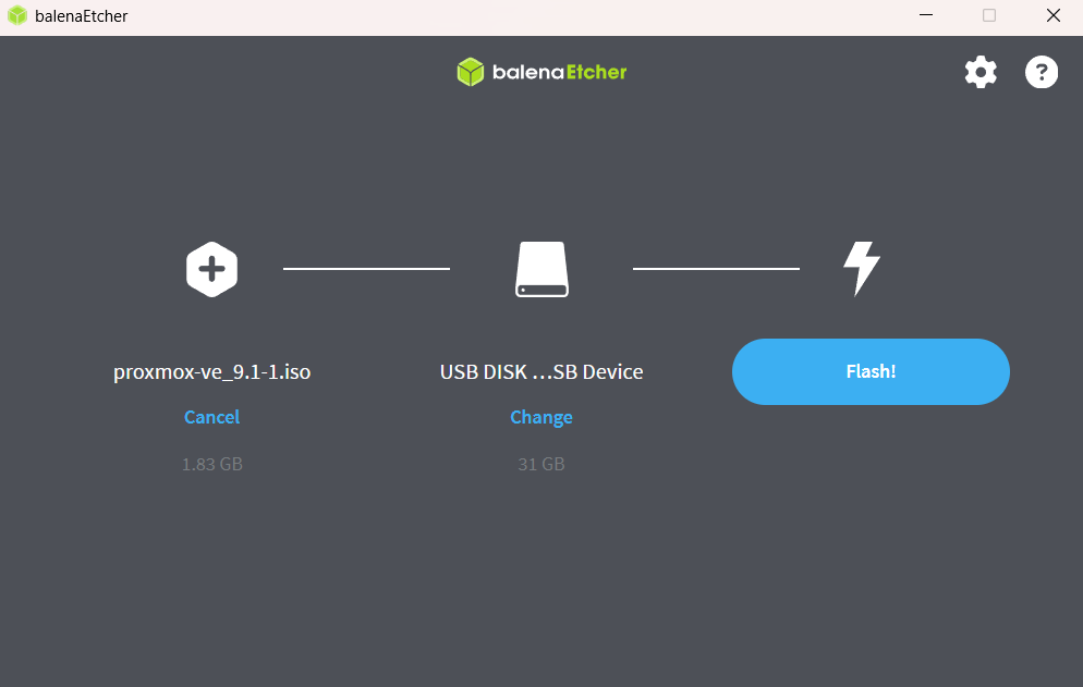
Once everything arrived, I grabbed a D1 Mini from my parts bin and started flashing ESPHome. Historically, I’ve had trouble getting ESPHome to talk to CH340‑based boards on Windows 11 — and this time was no different. Last time I had pulled out an old Windows 10 laptop to flash it but I decided to try to do some more digging and fix my Windows 11 setup.
After digging around, I found a Reddit thread recommending a different CH340G driver version. The GitHub repo looked sketchy at first, but it turned out to be from the official NodeMCU account. I uninstalled the old driver, installed the new one, and suddenly the ESPHome Web Flasher connected instantly.
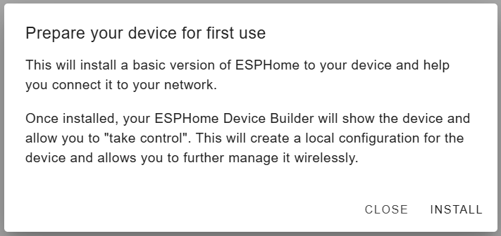
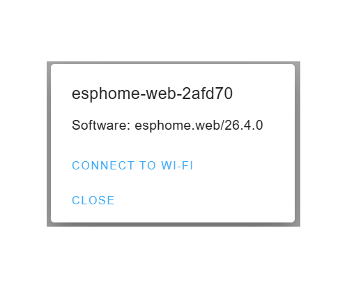
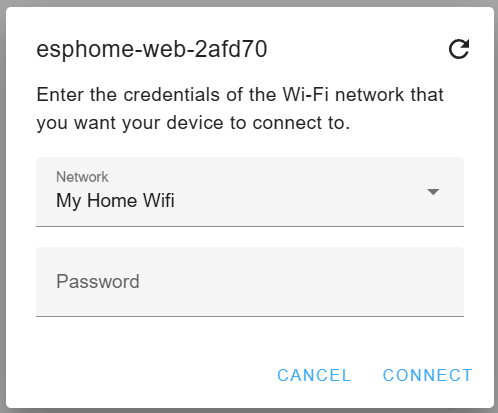
I flashed the initial ESPHome image, connected it to Wi‑Fi, and moved on.
Configuring the Board
Initial Setup
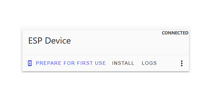
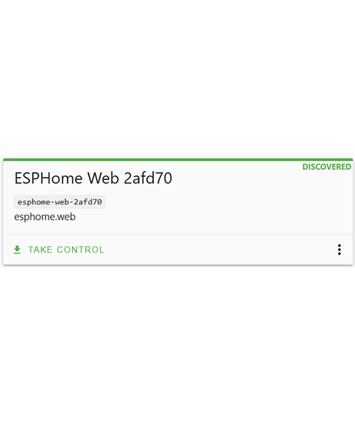
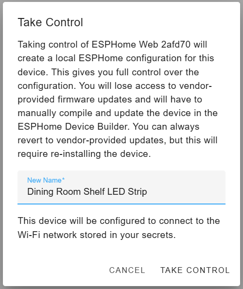
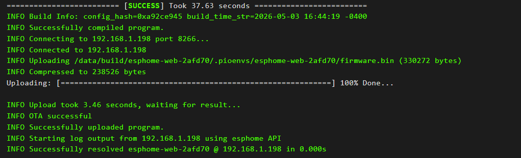
With the device online, ESPHome Device Builder immediately discovered it. I took control of the device, renamed it, compiled the config, and flashed it OTA.
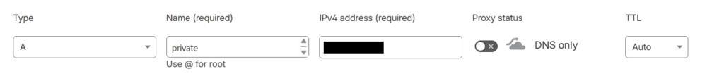
With the flash complete, it was time to customize the configuration. I added in some basic sensors for wifi signal and uptime as well as giving it a static IP (this required configuring a DHCP reservation in the router). The flashing tool usually relies on mDNS to discover devices but I have that disabled so instead I use a static IP.
Here is my initial config (most of these are self explanatory, but I’ve gone through what each of these is in detail in a previous post).
esphome:
  name: "esp-dining-room-shelf-light"
  friendly_name: Dining Room Shelf LED Strip
  min_version: 2025.11.0
  name_add_mac_suffix: false

esp8266:
  board: d1_mini

# Enable logging
logger:

# Enable Home Assistant API
api:
  encryption:
    key: !secret api_key

# Allow Over-The-Air updates
ota:
  platform: esphome
  password: !secret ota_password

wifi:
  ssid: !secret wifi_ssid
  password: !secret wifi_password
  manual_ip:
    static_ip: 192.168.1.198
    gateway: 192.168.1.1
    subnet: 255.255.255.0
  ap:
    password: !secret ap_password

binary_sensor:
 - platform: status
   name: "Controller Status"

sensor:
  - platform: wifi_signal
    name: "WiFi Signal Sensor"
  - platform: uptime
    type: seconds
    name: Uptime Sensor

text_sensor:
  - platform: wifi_info
    ssid:
      name: ESP Connected SSID
    mac_address:
      name: ESP Mac Wifi Address
  - platform: version
    name: "ESPHome Version"
    hide_timestamp: true
Home Assistant Configuration
With the basic sensors set up, it was time to bring the device into Home Assistant. I went to Settings -> Devices & Services and since I already had the ESPHome integration installed, Home Assistant immediately detected the new board.
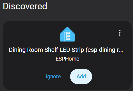
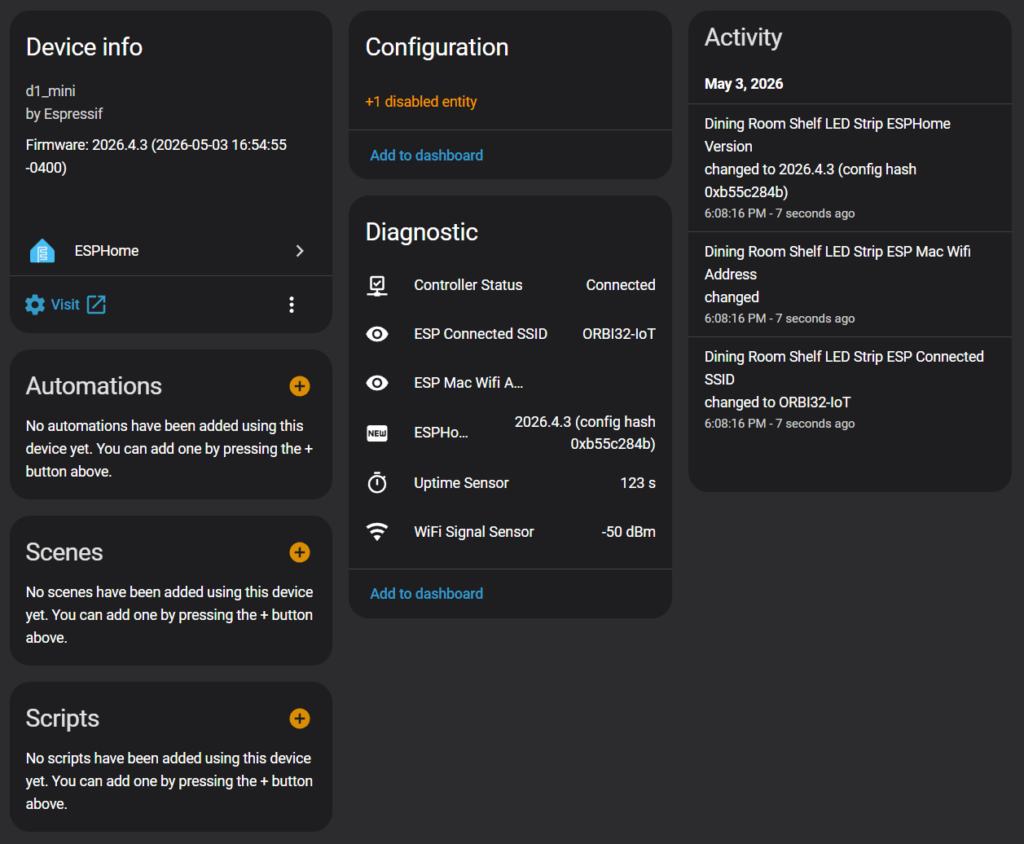
I clicked the button to add the new device, assigned a location and then added it to Home Assistant. I then went to the device page where I was able to see the new device and all the sensors I had configured. At this point, the board was talking to Home Assistant but it couldn’t control anything yet.
Configuring the Light Entity
With the basic tests complete, it was time to configure the light entity so that the board would be able to control an LED strip. Back in “ESP Home Device Builder” I added a PWM output on GPIO4 (D2) and created a monochromatic light entity tied to that output.
# --- OUTPUT DRIVER ---
output:
  - platform: esp8266_pwm
    id: white_strip_output
    pin: GPIO4  	 # D2
    frequency: 1000 Hz   # Smooth dimming, no audible noise

# --- LIGHT ENTITY ---
light:
  - platform: monochromatic
    name: "Dining Room Shelf LED Strip"
    output: white_strip_output
    default_transition_length: 0.3s
    gamma_correct: 1.0      # COB strips look more natural with gamma 1.0
    restore_mode: RESTORE_AND_OFF
After compiling and flashing, Home Assistant showed the new light entity (clicking on it displays the dimmer).

Hardware Setup
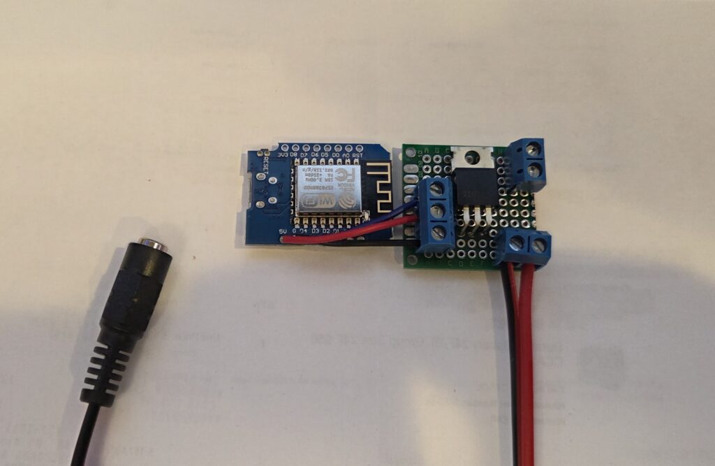
With the software side complete, I moved on to the hardware. I decided to mount everything on a small proto board using screw terminals for clean wiring. After some layout planning, I settled on a final arrangement.
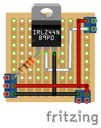
Soldering the Board
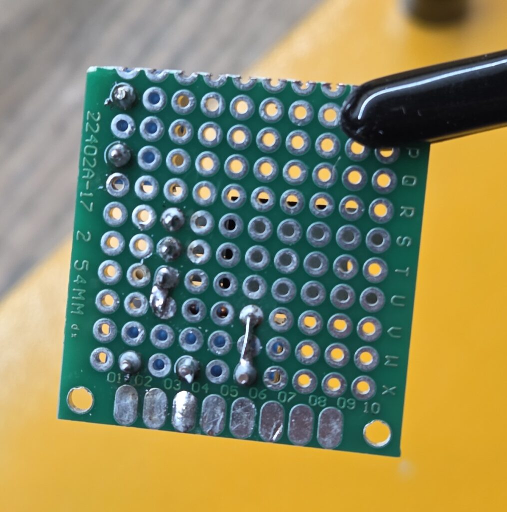
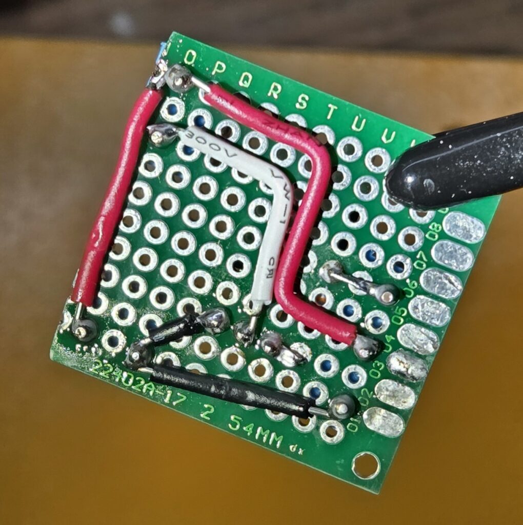
I started by placing all the components on the proto board to confirm spacing and plan out the wiring on the back.
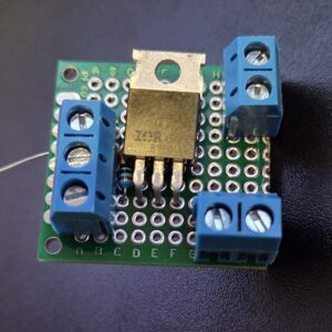
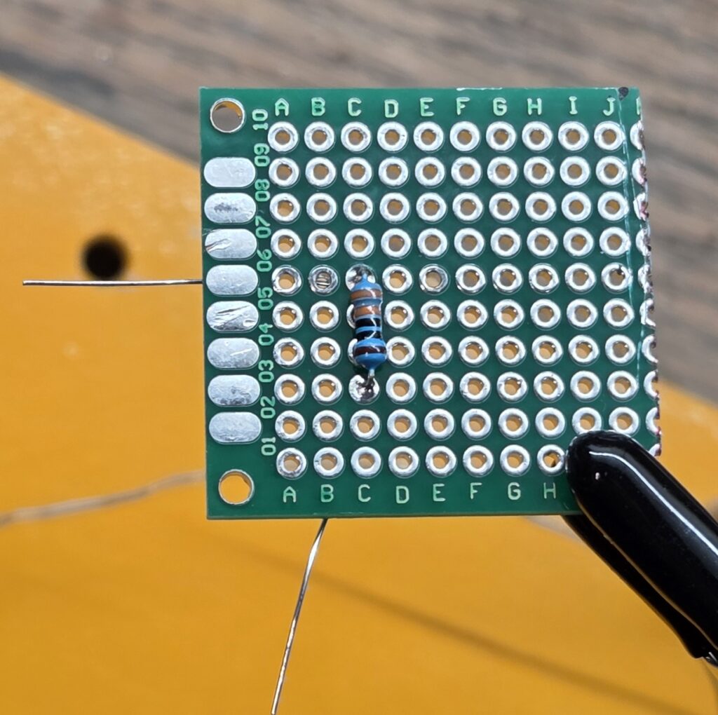
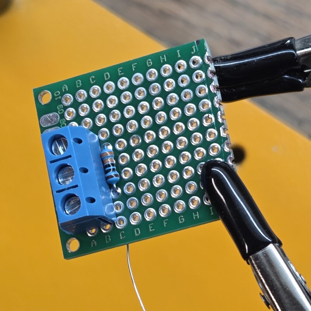
Once satisfied, I pulled everything off and soldered the components one by one. First came the resistor and the 3-pin screw mount terminal.
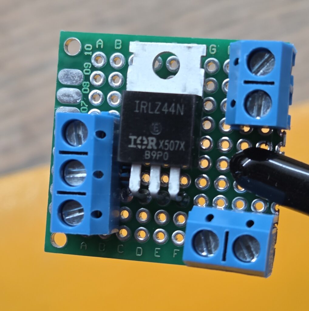
Next I added the transistor and bottom 2-pin screw terminal. And then finally the top 2-pin screw terminal. I reused the resistor legs to bridge the gate connection. They were perfectly positioned, and it saved me from running a tiny jumper wire.
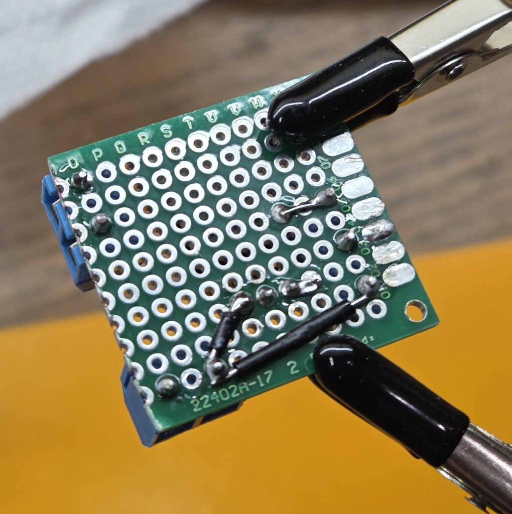
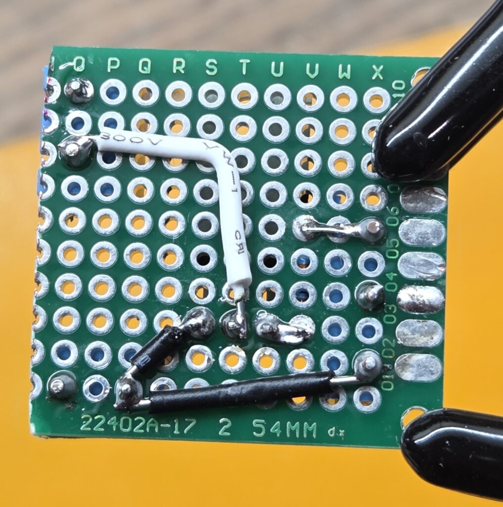
That was the easy part, next came all the connections on the back. First I added the ground cables, then the drain for the transistor and finally the power wires. This part took the longest, but the end result was tidy and solid.
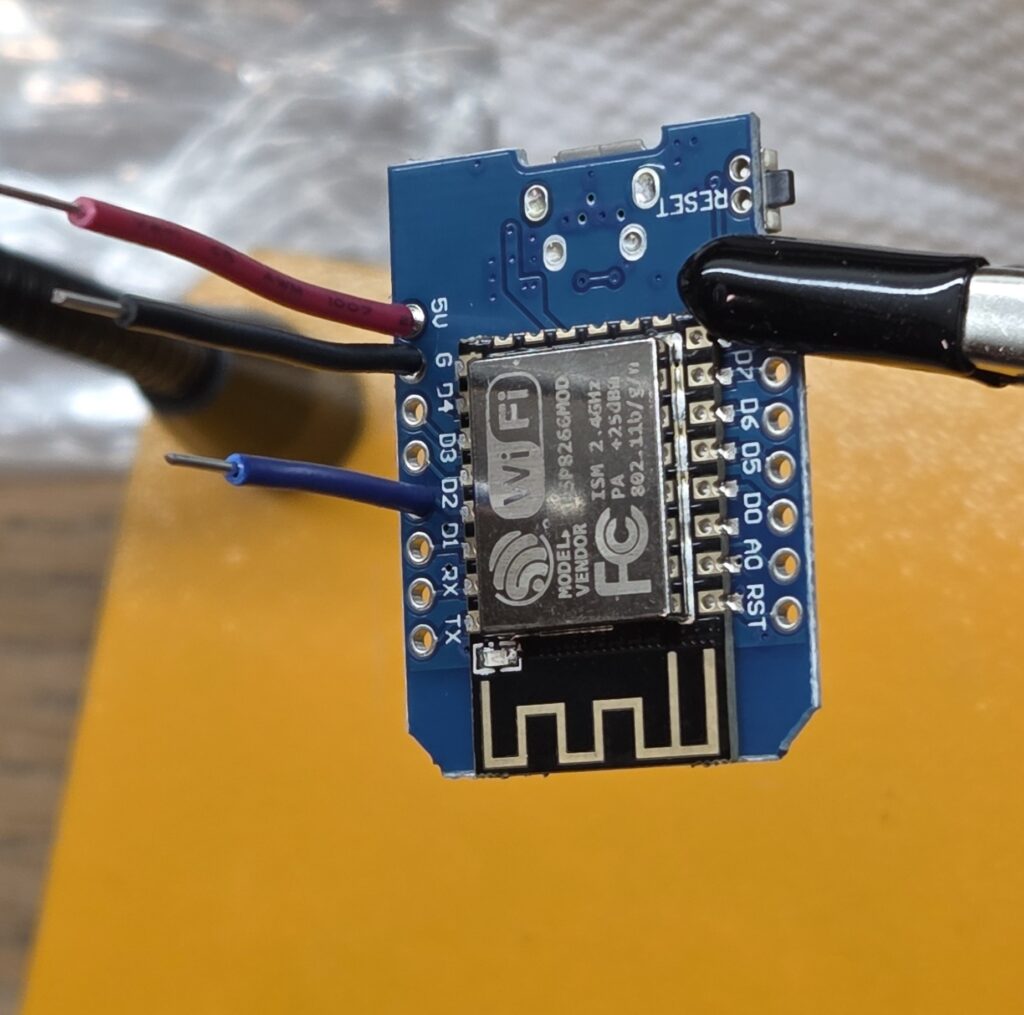
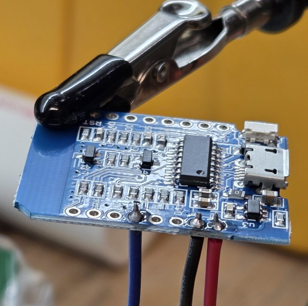
Soldering The ESP8266
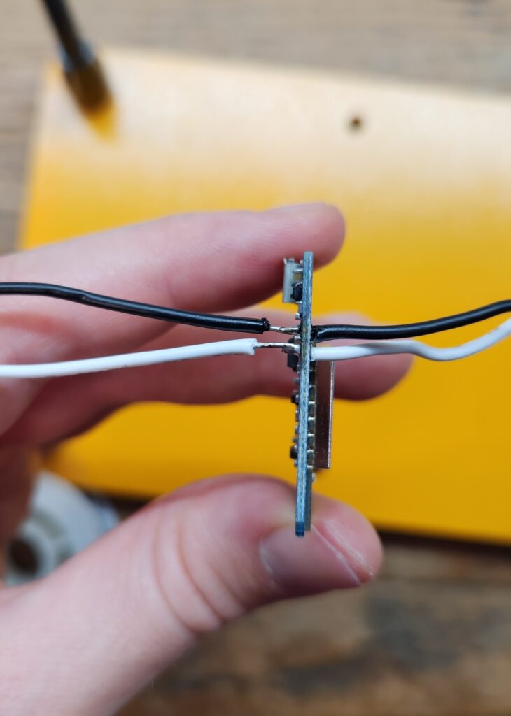
Compared to the proto board, soldering wires to the D1 Mini was trivial. A few quick joints and it was ready.
Testing the Connections
Before committing to installation, I tested everything on the bench. I used alligator clips to connect an LED strip and verified power delivery, MOSFET switching and dimming behavior.
Everything worked as expected. I then soldered leads onto the LED strips themselves and added heat shrink for strain relief.
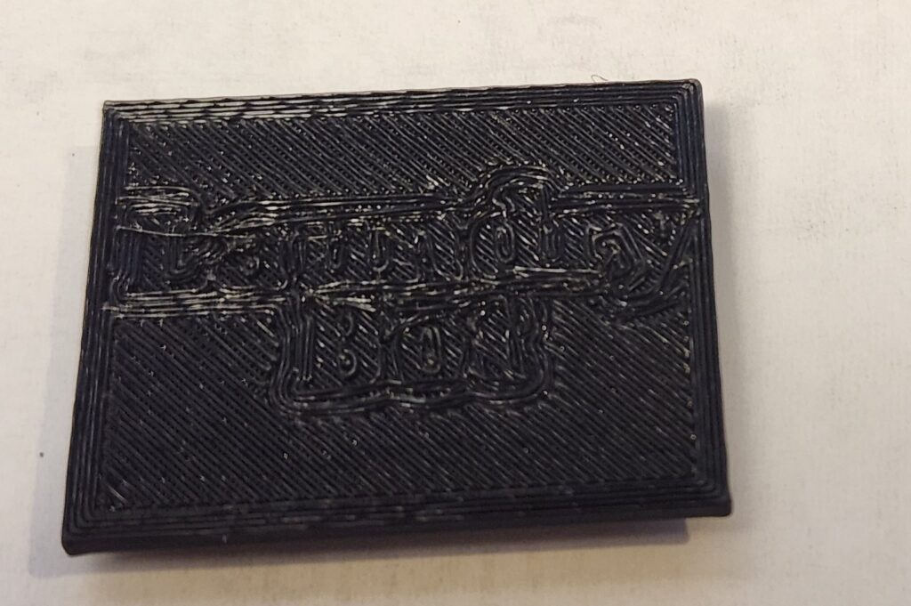
Creating a Case
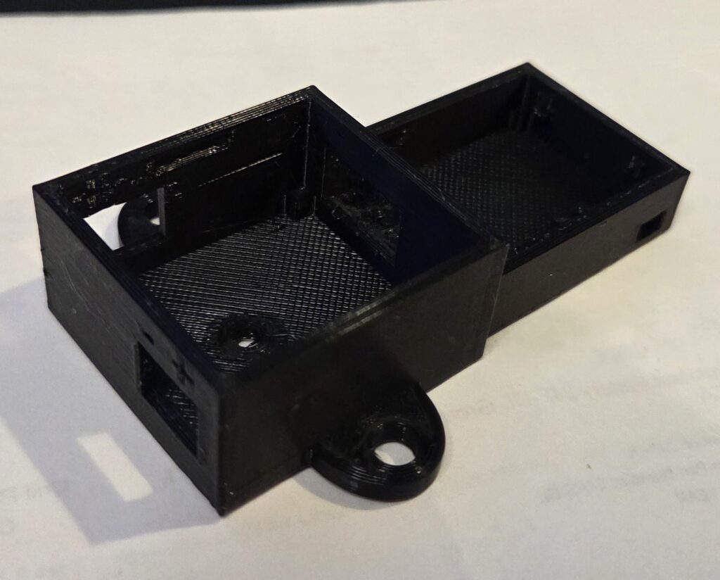
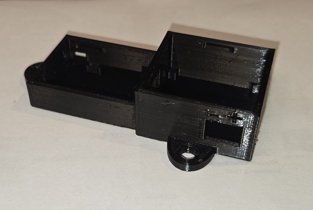
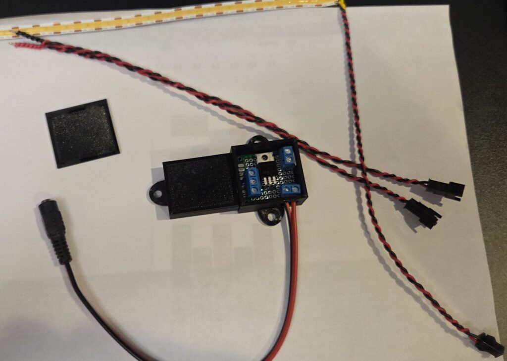
With all the hardware ready, I needed a case to mount this on the back of the shelf. I reused an ESP8266 case design from a previous project and modeled a matching enclosure for the proto board. I then cut out slots for all the connections I needed and added some mounting holes on the side so that I could attach it.
With the model ready, I printed the parts and test fit everything.
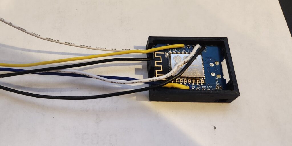
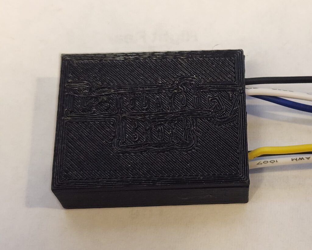
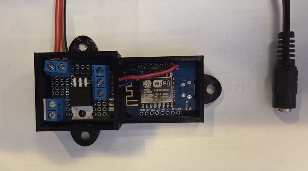
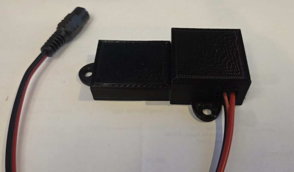
Then I put the ESP8266 and proto board into the case, connected them up, and attached a barrel jack adapter for power.
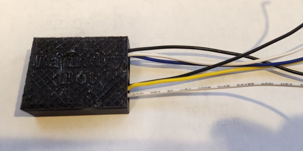
It all fit nicely, so I went ahead and printed some covers for the case
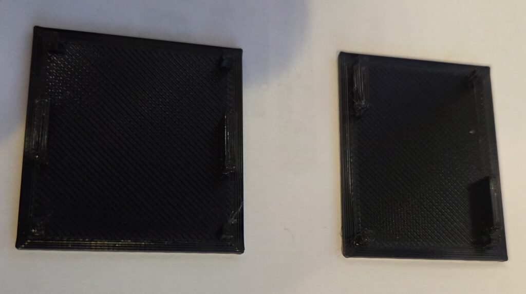
One corner post interfered with a screw terminal, so I trimmed it slightly. Once assembled, the case looked clean and compact.
Final Assembly and Testing
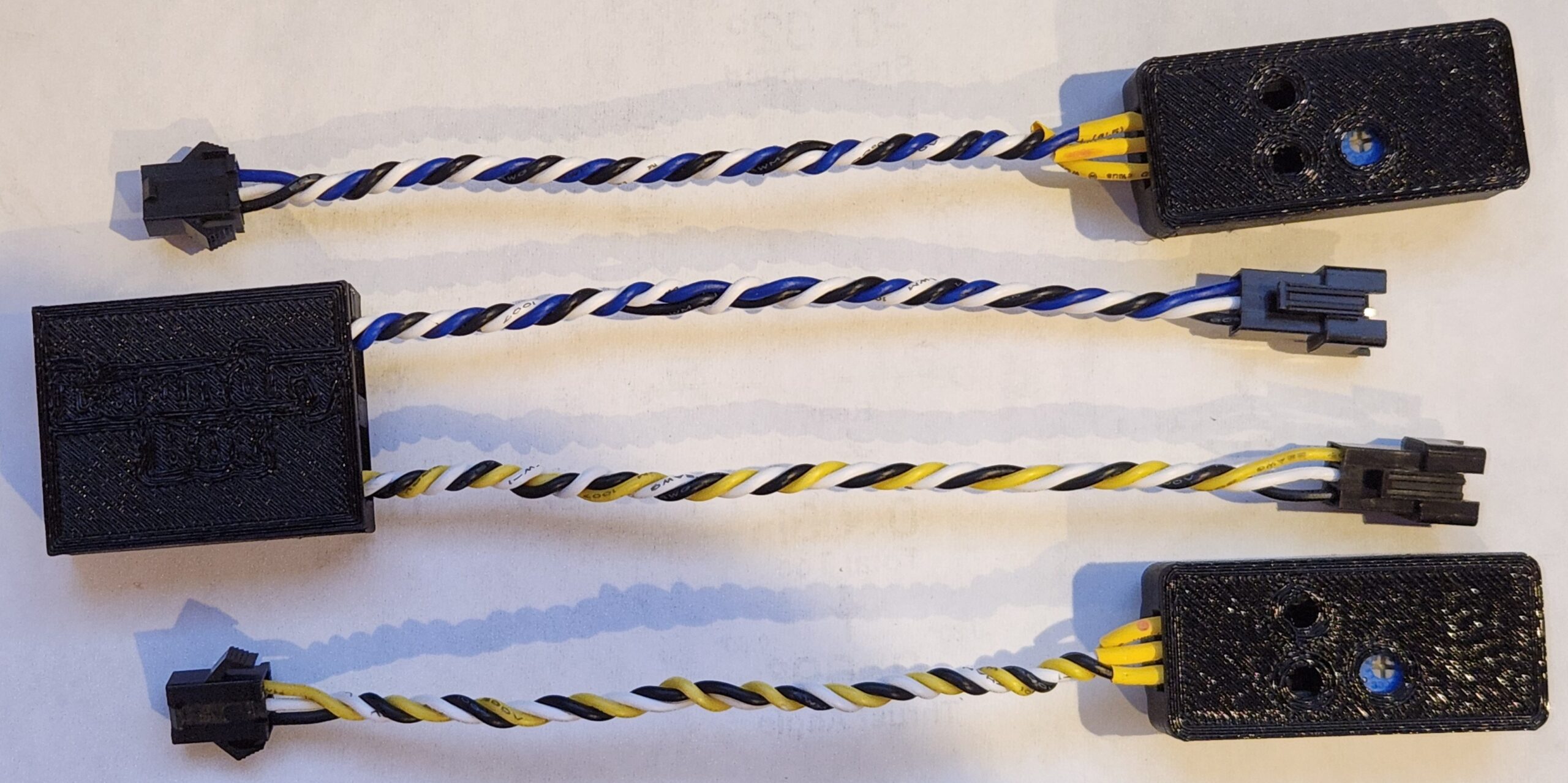
With everything looking good, I wanted to do one more test on the workbench before moving forward with installation. Since I planned to run two LED strips in parallel, I braided two sets of power wires and added JST connectors to the strips and the splitter.
A final bench test confirmed everything worked with both strips connected.
Installation
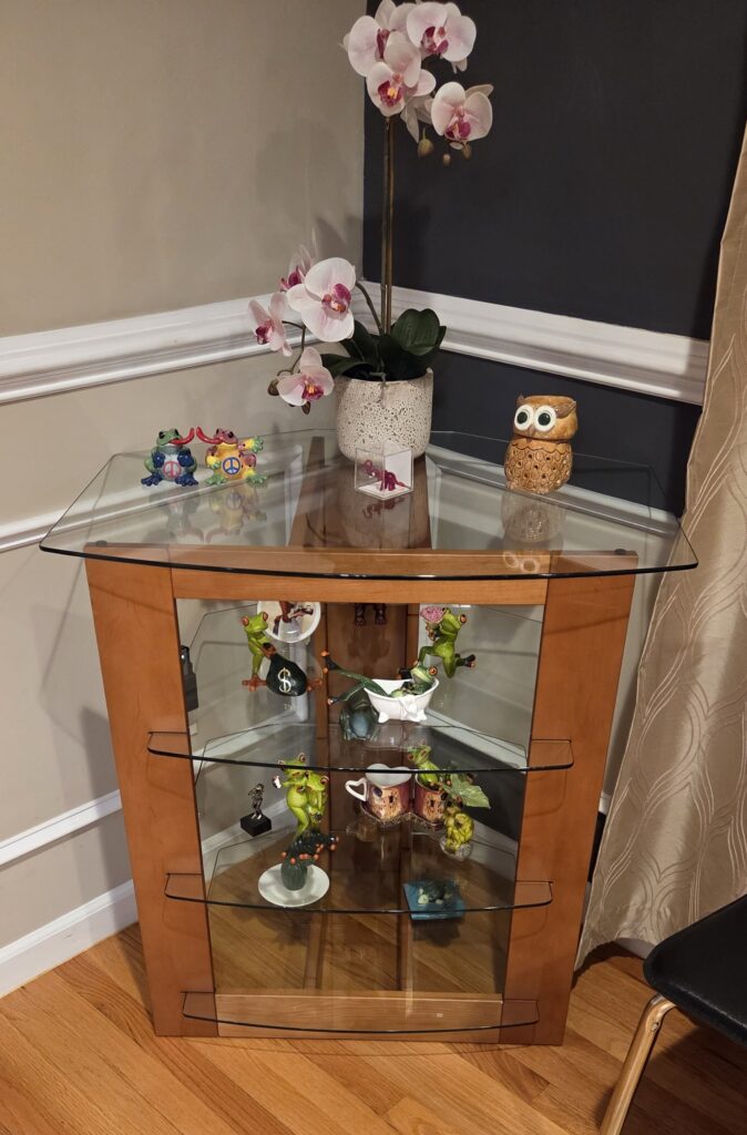
With everything tested it was time to proceed with the installation. Here’s the shelf before installation.
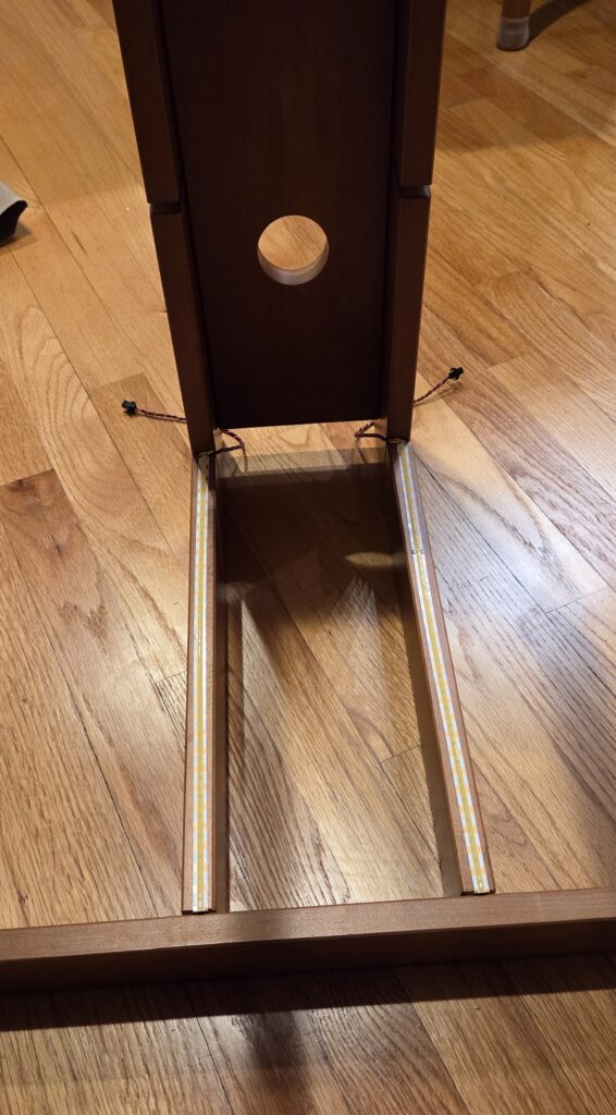
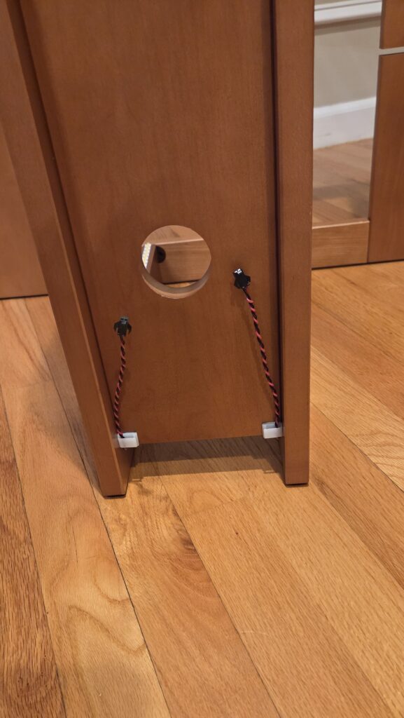
I cleared the shelves, removed the glass, and flipped the frame over to attach the LEDs. I then peeled the backing and attached the two LED strips along the center supports of the shelf. I’m not adding any additional mounting hardware for now, so time will tell how well the sticky backing holds up. I then routed the power cables over the back wall and secured them with some sticky wire clips.
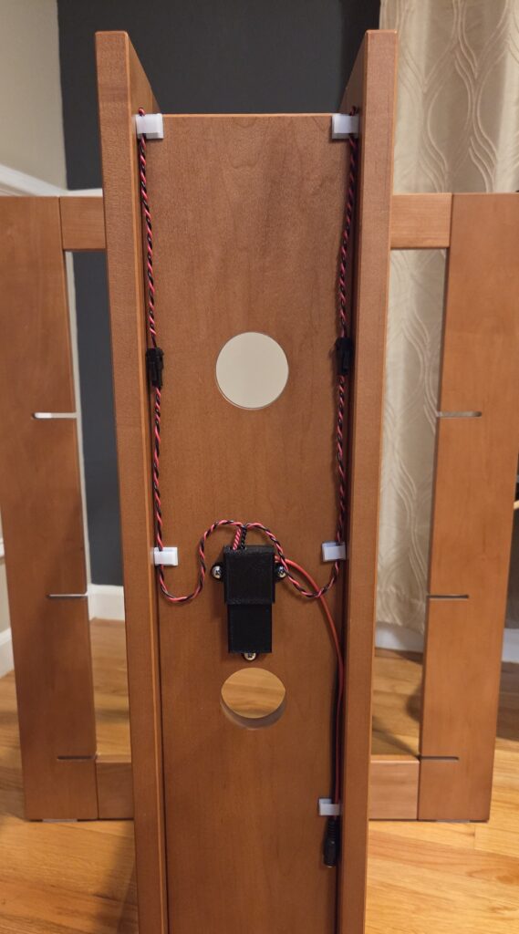
Then I found some screws and attached the case which had the ESP and proto board in it. The splitter I created for the LED strips had a bit of extra wire, which I tucked away (but better to have extra than not enough). I connected together all the wires and secured them with wire clips as well.
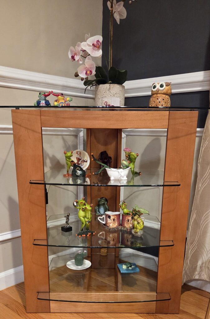
A quick test showed the lighting worked beautifully.
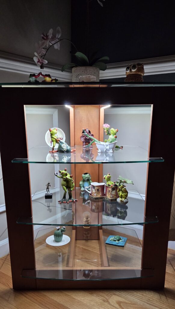
After reinstalling the glass and decorations, the final effect looked great. Here is how it looked (the camera struggled a bit with glare).
Wrap up
The finished project turned out really nicely, and my parents were thrilled with the result. It also leaves room for future Home Assistant automations, like turning the lights on at sunset or when motion is detected.
What I liked most about this build is that it was a practical application of things I’ve done before. Nothing overly complex, but a clean, satisfying project that solved a real need.