In Part 1, I built a proof-of-concept using an ESP8266 and vibration sensors to detect washer and dryer activity. The breadboard prototype had proved the idea worked, but it looked more like a science fair project than a laundry automation device. It was time to make it permanent. That meant dragging out the soldering iron, wrestling with too-thick wires, and learning to use heat shrink tubing along the way.
Of course, once the wiring was done, I needed a proper home for the controller and sensors. My 3D printer got a workout as I iterated through case designs — some good, some cracked, and some that never quite fit.
This part of the project was all about turning a fragile prototype into something that could survive real use, and as usual, the process wasn’t as straightforward as I first imagined.
Soldering
The Controller
With the breadboard test behind me, it was time to make things permanent. The ESP8266 D1 Mini only has one 5V pin and one ground pin, but I needed power for both sensors. My first thought was to try cramming two wires into a single hole — turns out, they were too thick for that.
So I improvised: I soldered one wire in normally, then cut the excess and attached another wire from the backside. Not the prettiest solution, but it worked.


Once everything was connected, I looked over the joints. Most were fine, but the extra wires I tacked onto the back left exposed sections that I wasn’t happy with. At first, I figured I’d just leave them — but the more I looked, the more it bothered me. This was the perfect excuse to try out some heat shrink tubing.
A quick Amazon order later, I slipped the tubing on, heated it up with the side of my soldering iron, and the results looked so much cleaner. Definitely worth the extra step.


It wasn’t flawless, but at least now the controller wiring looked sturdy enough to move on to the next stage.
The Sensors
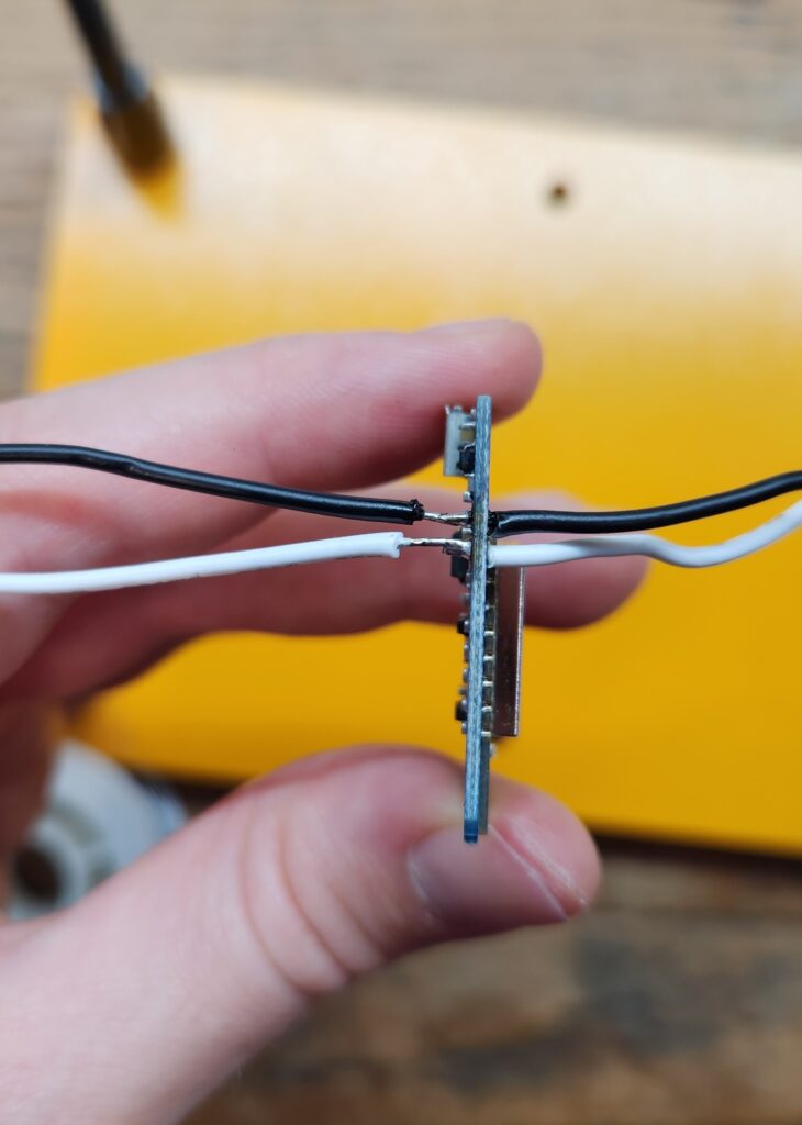
Next up were the SW-420 vibration sensors. These modules came with header pins pre-soldered, which was convenient for breadboarding but not ideal for my ultimate use case. I considered removing the headers, but they were stubbornly attached, and I didn’t want to risk damaging the board.
So instead, I decided to solder the wires directly onto the existing headers. This worked, but it was fiddly; the joints ended up with more exposed metal than I liked, and the connections didn’t look as neat as I wanted. Once again, heat shrink tubing came to the rescue. Sliding it over the messy joints and shrinking it down made everything look far cleaner — and much sturdier.


The sensors were now wired up solidly and ready to be paired with the controller.
3D Printing
The ESP Case
With the wiring done, I needed a proper case for the controller. I dug up an old model I had lying around and modified it with a few cutouts for the wires. Version 1 came off the printer looking decent… until I tried fitting the ESP inside.

The holes were too small, the support platform blocked the bottom wires, and the cover clips pressed right on top of my solder joints. In short: it didn’t fit.
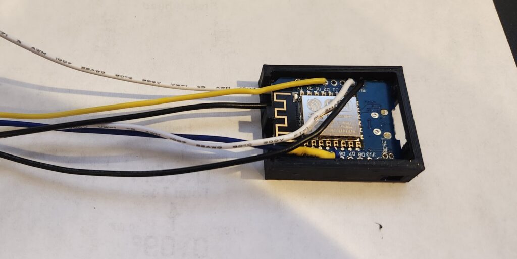
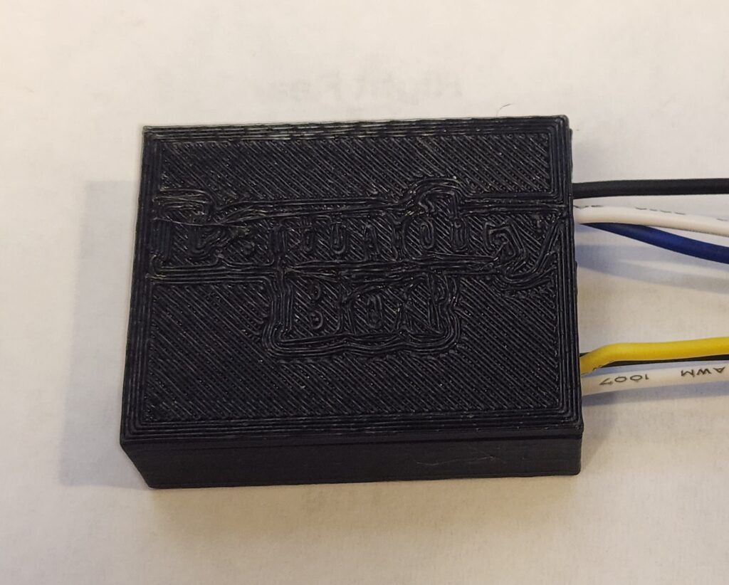
So I started over. For Version 2, I rebuilt the case from scratch. I fixed the tilt in the model, added full-height holes for the wires, moved the clips away from the solder joints, and even added some lettering to the cover.


The new case worked better and I was able to fit the D1 mini and cables, but the cover gave me headaches. I printed it with supports, which fused too tightly, and I ended up cracking it while trying to pry it apart. Not ideal. The ESP also did not sit as deep and snugly as I had hoped due to the wire underneath not allowing it to go all the way down but it was good enough.
I wasn’t ready to give up on the lettering, though. For Version 3, I changed the design so the text was cut into the cover instead of raised, and I printed it without support. This time, it came off cleanly without cracking.
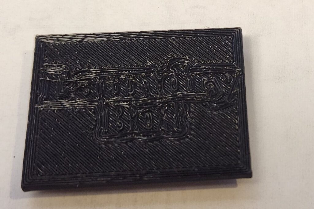
The lettering was subtle, but it worked, and the case finally felt solid enough to house the controller.

The Sensor Case
After finishing the controller case, I turned my attention to the vibration sensors. I found a case model on Thingiverse that looked promising, with cutouts for the adjustment screw and indicator LEDs.
I printed it out… and the sensor didn’t fit. Too tight, wrong alignment, and no room to slide it in cleanly. So, back to the design software. I stretched the model, shifted the pillar that holds the sensor, and shortened the height a bit so it would sit snug. The first reprint was better, but still not quite right. It took one more iteration to finally get the case fitting the SW-420 modules properly.


The result was a simple but sturdy enclosure that kept the sensors secure while still exposing the adjustment screw. It wasn’t fancy, but it worked — and the sensors finally had a proper home.
Finishing Touches
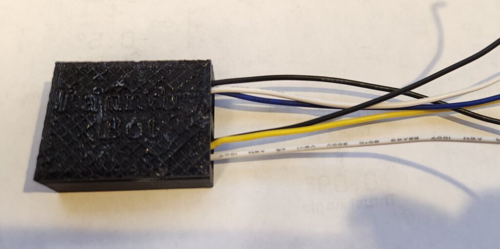
With the controller and sensors each in their own cases, the last step was cleaning up the wiring. At this point, I had a jumble of wires sticking out in all directions, and I didn’t want to leave them loose.
So, I twisted the wires together into neat bundles, then crimped on JST connectors. That way, the sensors could be easily plugged in or disconnected without having to resolder anything.
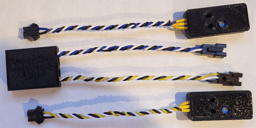
It was a small detail, but it made the whole project feel much more polished. The wiring was tidy, modular, and finally looked like something I could install next to the washer and dryer.
Ready to Install
After plenty of soldering, shrinking, printing, and re-printing, the hardware was finally taking shape. The ESP had a case that fit, the sensors had snug enclosures, and the wiring was cleaned up with connectors.
What started as a breadboard full of loose jumpers now looked like a real device. It was finally ready to move out of the workshop and into the laundry room.
In the next part, I’ll tackle the final configuration, mounting the sensors to the machines, and getting the system up and running in Home Assistant.